
v0.1IN PROGRESS
Coming soon- Constraint-based 2D sketcher driven by a Newton-Raphson solver
- Seventy-two geometric and dimensional constraint types
- Degree-of-freedom analysis that drives entity colour and the DOF overlay
Professional design tools shouldn’t be out of reach.
Pingendum is a parametric CAD application being developed for 2D and 3D design. Its initial release is a precise, constraint-based 2D CAD sketching environment built for engineers, designers, students, makers and small manufacturers who need a more accessible way to turn ideas into real designs. 3D solid modelling is currently in development as the next stage.
Pingendum began with a straightforward frustration: professional CAD tools can be expensive, particularly for people building independently or starting small.
Students may have access through educational programmes. Large companies can budget for professional software. But the gap can still be significant for the independent engineer, maker, small manufacturer, or person trying to turn an idea into something real.
Henrik Pryter started Pingendum after experiencing that barrier firsthand. The goal was simple: build precise design tools that are within reach of the people who need them.
Henrik PryterFounder
Build the idea. Not the software bill.
The common thread isn’t a job title. It’s needing a drawing to be exact without needing an enterprise CAD setup to get there.
For precise 2D geometry and technical sketches that need to hold their dimensions.
For turning concepts into dimensioned designs that can be shared and built from.
For learning constraint-based design when educational access isn’t available or doesn’t fit.
For designing parts that are going to be cut, printed, machined or built for real.
For shops that need practical drawing tools without the cost structure of enterprise CAD.
For people developing their own ideas without a large company or engineering team behind them.
Pingendum is for the drawing you intend to make something from. Every dimension below drives the geometry it measures — change the value and the part follows.
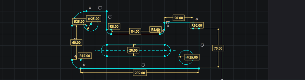
Stepped bracketTwelve dimensions — overall length and height, two notch radii, a corner radius, two hole diameters and a slot width. Every one of them drives the geometry it measures.
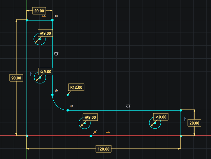
Angle bracketNine dimensions — 120 along the base, 90 up the upright, a 20 wall on each leg, an R12 fillet where they meet, and four 9.00 holes. Drawn from typed lengths and absolute angles, one segment at a time.
Closed profiles with steps, notches and radii, dimensioned end to end so the shape is defined rather than approximated.
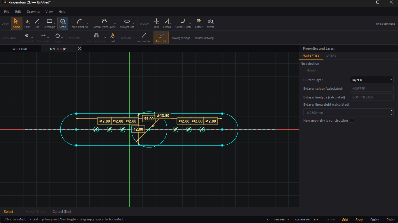
Mounting holes and bolt circles placed to dimension instead of by eye. The servo horn in the hero carries six of them at 2.00.
Straight slots drawn to a typed length and width, then trimmed into the surrounding profile.
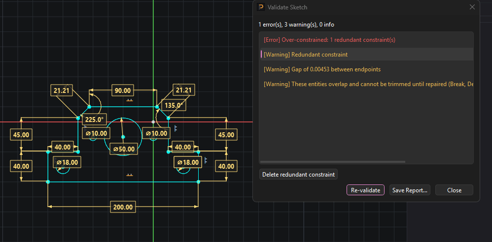
Corner treatments applied in the sketch and carried by the solver. The bearing pedestal below closes with two 21.21 chamfers at 135 and 225 degrees.
Driven dimensions that measure without over-constraining, and construction lines that guide without joining the profile.
DXF for the next tool in the chain, or a plotted PDF sheet for someone who just needs to read it.
The degree-of-freedom count tells you how much freedom is left, and unconstrained geometry stays cyan until you pin it down.
When constraints clash, the panel marks the specific ones that are redundant instead of failing the whole solve.
Validate Sketch names duplicate lines, overlaps and open contours before they break a downstream feature — and offers the repair.
Dimensions drive the geometry. Change a value and everything constrained to it follows, exactly as you defined it.
Three captures of the sketcher on real drawings, and what it tells you when something is wrong.
The solver re-runs after every edit and reports what the sketch has left to pin down. Under-constrained gives you the count. Over-constrained tells you how many constraints are redundant. A genuine conflict is named as its own state rather than hidden inside a failed solve. One readout, four answers — so a sketch that will not resolve tells you which kind of wrong it is.

A contradiction does not fail the whole solve. Pingendum separates a genuine conflict — a new constraint the sketch cannot satisfy at any size — from mere redundancy, names the one constraint at fault, and offers to delete precisely that one. You remove the constraint you meant to remove, not the one you guessed at.
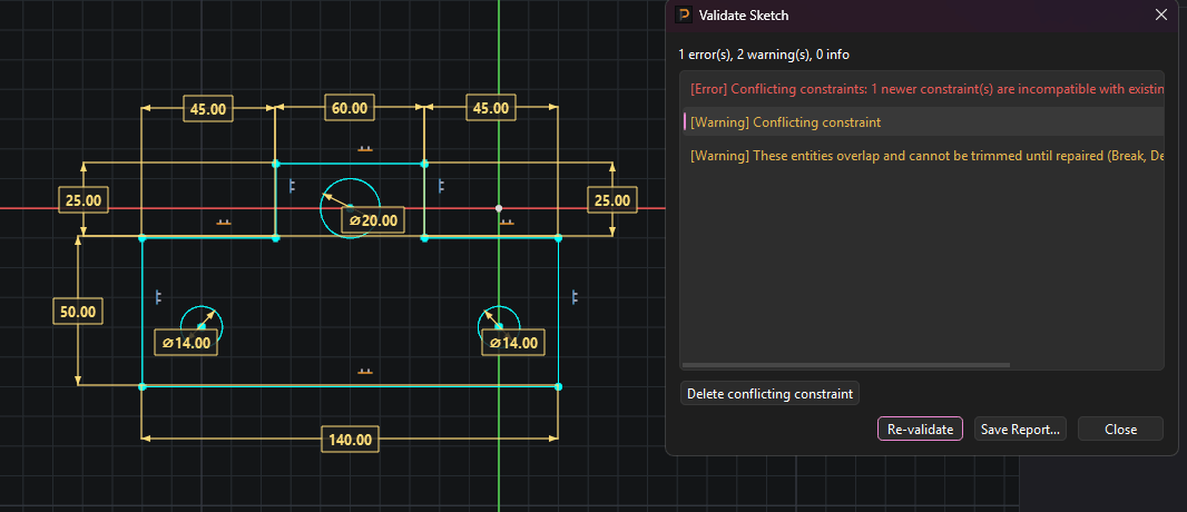
Validate Sketch names every problem it finds — redundant constraints, duplicate lines, entities that overlap and cannot be trimmed until repaired — and offers the repair alongside it.
Draw the profile.
Change what you have drawn.
Define how geometry relates.
Give it numbers, and read what is left.
Pingendum is a parametric CAD application for 2D and 3D design. The 2D sketching environment is the part that is finished, so it is the part being released first.
Geometry, the full constraint toolkit, degree-of-freedom feedback, diagnostics, grid snap, drafting aids and reference dimensions.
Pad, pocket, revolve, fillet, chamfer, shell and patterns are already built. They are not what this first release is for, and will arrive in a later build with the documentation that covers them.
Projects save to Pingendum’s own versioned format. Drawings import and export as DXF — R12 or R2000, geometry on layer 0 and construction geometry on its own layer — though dimensions and constraints are not carried across, because DXF has no way to represent them. Drawings also plot to a PDF sheet or a printer at a real scale, with an ISO title block and hidden, frozen and non-plot layers left off the paper. There is no DWG, STEP or STL export.
On the long-term roadmap only. Neither is promised for a date, and neither is being sold to you today.
Work beyond the sketcher is tracked in the changelog as it lands, and the documentation covers the sketcher chapter by chapter.
Pingendum is under active development ahead of its 2D release. Every update is logged — no silent changes.
The 2D sketcher is being prepared for its first release. Join the waitlist to be notified when early access opens.